Filter on ALL, SYNTH, DRUM, SAMPLER or MISC |
Total list currently 2405 items in 330 Brands |
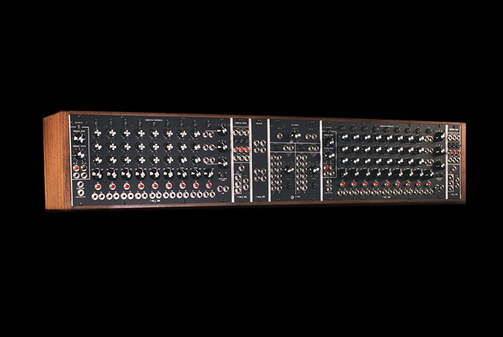
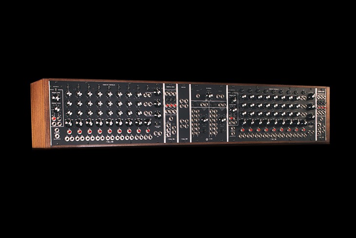
Moog | Sequencer Complement B |
|
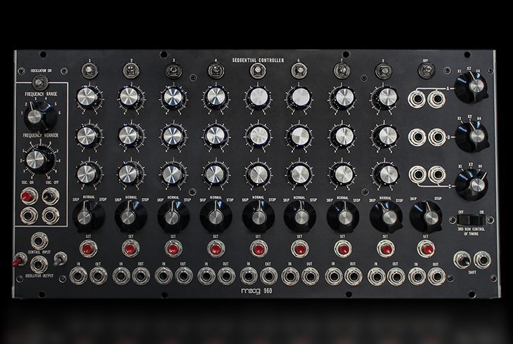
Description | Faithfully Recreating The Sequencer Complement B Expansion Cabinet Three years of research and design has culminated in Moog Music recommencing the manufacturing of a limited number of Moog System 55, System 35, Model 15 modular synthesizers and the Moog Sequencer Complement B. Using all of the original documentation, as well as the original circuit board and art files, Moog engineers have hand-built true recreations of the original instruments based on their 1973 factory specifications. Each Sequencer Complement B expansion cabinet is hand-built to its original 1974 Moog factory specifications and is a true recreation of the original. Individual modules are brought to life just as the originals were, by hand-stuffing and hand-soldering components to circuit boards, and using traditional wiring methods. Each module is then finished with a photo-etched aluminum panel, and placed in its new modular instrument. This limited reissue of the Moog Sequencer Complement B expansion cabinet is built to order, and is available in limited quantities while parts remain. Over the course of 3 years Moog Music set out to research and build faithful recreations of the System 35, System 55 and the Moog Sequencer Complement B expansion cabinet. Using all original documentation as well as circuit board and art files for every module, Moog Engineers have painstakingly recreated this rare creative gem. Each Sequencer Complement B expansion cabinet is hand-built to its original 1974 Moog factory specifications and is a true recreation of the original. Individual modules are brought to life just as the originals were, by hand-stuffing and hand-soldering components to circuit boards, and using traditional wiring methods. Each module is then finished with a photo-etched aluminum panel, and placed in its new modular instrument. The 960 Sequential Controller has a wide variation of functions, both as an independent module and in combination with the 961Interface and 962 Sequential Switch. The sequencer module consists of a voltage controlled clock oscillator, which drives three rows of eight steps each. Indicator Lights show sequence and step position status. A separate potentiometer for each step permits up to eight different voltage settings to be selected for each row. The DC voltage output corresponds to the column of pots below the lighted stage. Voltage Range switches for each row determine the DC voltage range ofeach pot with two volts {X1}, four volts {X2}, or eight volts{X4} maximum extent. Two parallel outputs are provided for each row. Jacks for trigger inputs and outputs appear below each column. Trigger inputs activate that stage independently of the clock oscillator trigger. Trigger outputs are available for any other V-trigger activated input. Manual trigger buttons as well,are included for each of the eight stages {found below the V-trigger jacks}. Switches found immediately below each step position permit normal, skip or stop functions. A ninth position providing skip {continuous progression through the eight steps}or stop {one progression to closure} functions is included at the end of the row. Timing control for the eight steps is accomplished via the Third Row Control of Timing switch. This switch connects the third row of the sequencer into the control input of the clock speed for each stage according to the settings on the third row potentiometers. The Shift input admits an external clock input to the sequencing circuit. This input may be used in addition to or exclusive of the internal clock oscillator trigger. Manual shift from step to step is accomplished with the button next to the shift input jack, as well as individual manual trigger buttons for each step found under each step column. Manual buttons or external v-trigger sources initiate the clock oscillator start and stop functions. The clock oscillator is capable of producing frequencies from .1Hz to 1kHz. It has both octave {range} and vernier {fine adjust} controls. One control input jack is available, as well as one rectangular wave output {approximately 90/10% duty cycle}. The clock oscillator, like other Moog oscillators, is standardized to one volt per octave. Four independent circuits are found on the 961 Interface: one Audio-In to V-trigger Out circuit, one S-trigger In to V-Trigger Out circuit, and two V-trigger In to S-trigger Out circuits. All interface circuits may be used simultaneously, in combination, or separately. The Audio to V-trigger circuit generates V-triggers when the audio input level rises above the threshold set on the Sensitivity potentiometer. This V-trigger sensitivity varies with the frequency band of the audio signal and with the frequency of its amplitude peaks. V-trigger duration is commensurate with the length of time the audio signal remains above the sensitivity threshold. Two parallel V-trigger outputs are included. Each V-trigger In to S-trigger Out circuit has two columns of six jacks each for input triggers and one S-trigger output. Column A of the V-trigger inputs will convert V-trigger signals to S-triggers with duration equal to the input. Column B determines S-trigger duration by the Switch-on-time knob ONLY. B Column S-triggers will block, extend or fore-shorten Column B V-trigger inputs to conform to whatever duration is indicated on the B-column potentiometer. A minimum switch-on-time of 40 milliseconds and maximum time of 4 seconds duration is available. Simultaneous inputs to both A and B columns may be made. Simultaneous inputs to two parallel jacks will result in the longer of the two trigger signals being accepted. 962 Sequential Switch: The 962 Sequential Switch selects between two or three signal inputs, coupling one signal to the output jack at a time. A V-trigger pulse introduced to the Shift Input initiates the sequence. The Sequential Switch will alternate between stages One and Two, disregarding stage three until a standard {tip-sleeve} phone plug is patched into Signal Input Three. A connection to Input Three will cause the Sequential Switch to alternate between the three stages {in order) when triggered. Separate V-trigger input and output jacks are provided far each of the three stages, as well as buttons for manual switching. A small light for each stage indicates its status, on {coupled to the output} or off. 994 Dual Multiples Panel: The multiple is a device, which permits multiple distribution of one signal to several different places. This process is often called signal splitting. Multiples are used for many purposes; from linking two patch cords together, sending a single signal to several different modules at the same time, to doubling or trebling the amplitude of a signal by sending it X3 to a particular source. |
| Brand | Moog |
| Model | Sequencer Complement B |
| Device | Misc |
| Type | Desktop |
| Engine Type | Controller |
| Engine | Sequencer |
| Sequencer | 2x (3 row 8step) |
| Keys | 0 |
| Key type | N/A |
| Velocity | N/A |
| Aftertouch | N/A |
| CV-gate | CV/GATE |
| Produced: | 2015 |
| Legend: | Obvious | Y: Yes, N: No, N/A: Not Applicable | |
| VCO | Voltage Controlled Oscillator | DCO | Digital Controlled Oscillator |
| LFO | Low Frequency Oscillator | Sub | Sub Oscillator |
| VCF | Voltage Controlled Filter | VCA | Voltage Controlled Amplifier |
| Velocity | As with a piano, the harder you hit a key, the louder the sound, unlike most organs which always produce the same loudness no matter how hard you hit a key. | Aftertouch | Pressing a key after you activated it. Channel Aftertouch, no matter which key, it will send a Channel message. Poly Aftertouch, sends the pressure per key instead of the whole channel. |
| Values for OSC, LFO, Filter, Envelope are per voice unless stated otherwise. | |||